State three rules concerning parallel circuits – In the realm of electrical circuits, parallel circuits play a crucial role. This article delves into the intricacies of parallel circuits, exploring three fundamental rules that govern their behavior. These rules provide a comprehensive understanding of how current, voltage, and resistance interact within parallel circuits, empowering engineers and enthusiasts alike to harness their capabilities effectively.
As we embark on this electrical journey, we will unravel the mysteries of parallel circuits, shedding light on their unique characteristics and practical applications. Prepare to be enlightened as we illuminate the principles that govern these intricate networks.
State Three Rules Concerning Parallel Circuits

Parallel circuits are electrical circuits in which the components are connected side by side, rather than in series. This allows the current to flow through each component independently, and the voltage across each component is the same.There are three main rules that govern the behavior of parallel circuits:
Electrical Current in Parallel Circuits: State Three Rules Concerning Parallel Circuits

Current Distribution in Parallel Circuits
In a parallel circuit, the current is distributed among the different branches of the circuit in inverse proportion to their resistances. This means that the branch with the lowest resistance will carry the most current, and the branch with the highest resistance will carry the least current.
Relationship between Current and Resistance in Parallel Circuits
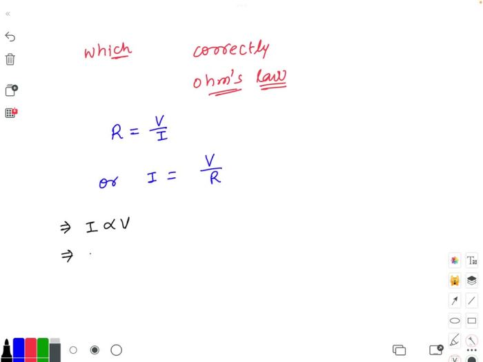
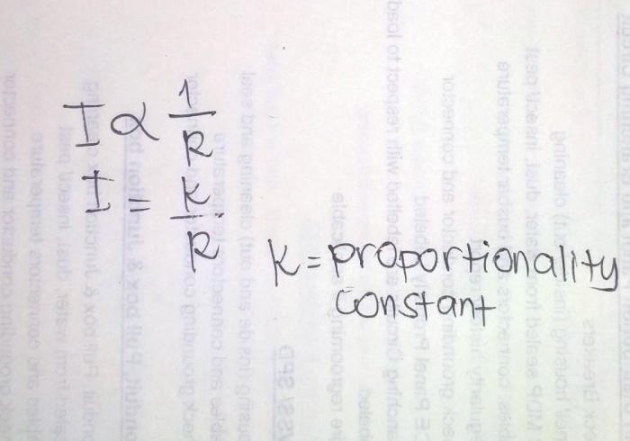
The relationship between current and resistance in a parallel circuit can be expressed by the following equation:“`I = V / R“`where:* I is the current in amps
- V is the voltage in volts
- R is the resistance in ohms
Example of Current Flow in a Parallel Circuit
Consider a parallel circuit with three branches, each with a different resistance. The branch with the lowest resistance will carry the most current, followed by the branch with the next lowest resistance, and so on.
Voltage in Parallel Circuits

Voltage Distribution in Parallel Circuits
In a parallel circuit, the voltage across each branch of the circuit is the same. This is because the voltage source is connected directly to each branch, and there is no resistance to impede the flow of current.
Relationship between Voltage and Resistance in Parallel Circuits
The relationship between voltage and resistance in a parallel circuit can be expressed by the following equation:“`V = IR“`where:* V is the voltage in volts
- I is the current in amps
- R is the resistance in ohms
Example of Voltage Distribution in a Parallel Circuit
Consider a parallel circuit with three branches, each with a different resistance. The voltage across each branch will be the same, regardless of the resistance of the branch.
Resistance in Parallel Circuits
Calculating Resistance in Parallel Circuits
The resistance of a parallel circuit is calculated by adding the reciprocals of the resistances of the individual branches. This can be expressed by the following equation:“`/ R = 1 / R1 + 1 / R2 + … + 1 / Rn“`where:* R is the resistance of the parallel circuit
R1, R2, …, Rn are the resistances of the individual branches
Relationship between Resistance and Current in Parallel Circuits
The relationship between resistance and current in a parallel circuit can be expressed by the following equation:“`I = V / R“`where:* I is the current in amps
- V is the voltage in volts
- R is the resistance in ohms
Example of Calculating Resistance in a Parallel Circuit
Consider a parallel circuit with three branches, each with a resistance of 10 ohms. The resistance of the parallel circuit can be calculated as follows:“`
- / R = 1 / 10 + 1 / 10 + 1 / 10
- / R = 3 / 10
R = 10 / 3R = 3.33 ohms“`
Power in Parallel Circuits

Calculating Power in Parallel Circuits
The power dissipated in a parallel circuit is the sum of the power dissipated in each branch of the circuit. This can be expressed by the following equation:“`P = P1 + P2 + … + Pn“`where:* P is the total power dissipated in the circuit
P1, P2, …, Pn are the power dissipated in each branch
Relationship between Power and Resistance in Parallel Circuits
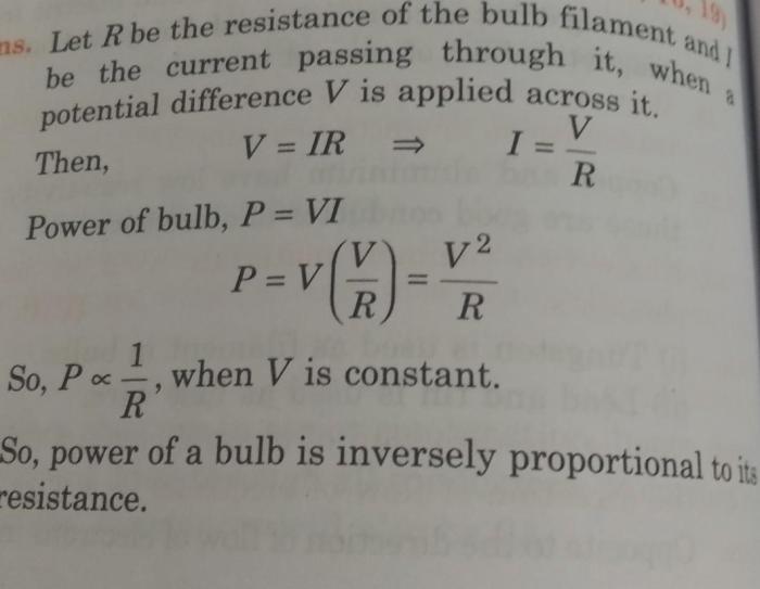
The relationship between power and resistance in a parallel circuit can be expressed by the following equation:“`P = V^2 / R“`where:* P is the power in watts
- V is the voltage in volts
- R is the resistance in ohms
Example of Calculating Power in a Parallel Circuit, State three rules concerning parallel circuits
Consider a parallel circuit with three branches, each with a resistance of 10 ohms and a current of 1 amp. The power dissipated in each branch can be calculated as follows:“`P = V^2 / RP = (1)^2 / 10P = 0.1 watts“`The total power dissipated in the circuit is:“`P = P1 + P2 + P3P = 0.1 + 0.1 + 0.1P
= 0.3 watts“`
Clarifying Questions
What is the key difference between series and parallel circuits?
In series circuits, components are connected in a single path, while in parallel circuits, components are connected in multiple paths.
How does current flow in a parallel circuit?
Current divides and flows through each branch of the circuit independently, with the total current being the sum of the branch currents.
What is the relationship between voltage and resistance in a parallel circuit?
Voltage remains constant across all branches of a parallel circuit, regardless of the resistance of each branch.